

Table of Contents
How to Splice Fiber Fusion and Mechanical Splicing. Every fiber network eventually needs a permanent joint: a cable gets cut, a drop must be extended, or a pigtail has to be connected to a feeder cable inside a distribution box. That joint is a splice, and how you make it affects loss, reliability, and long-term maintenance cost.
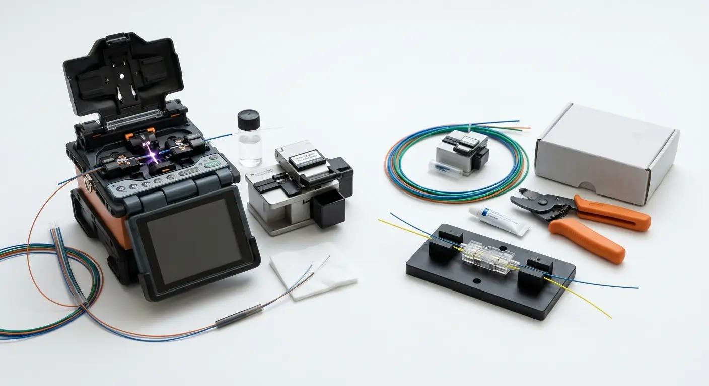
There are two proven methods: fusion and mechanical splicing. This guide explains how each works, walks through the process, and helps you choose the right one for the job.For FTTH points, a clean layout with PLC splitters and labeled pigtails saves hours during future maintenance.
What Is Fiber Splicing?
Splicing joins two bare fibers end to end so light passes from one to the other with minimal loss and reflection. Unlike a connector, which can be unplugged, a splice is meant to be permanent.
Splices are used to:
- Terminate cables with pigtails inside fiber boxes and closures
- Repair damaged cables
- Join long runs where a single cable length is not enough
- Build FTTH distribution points and branch networks
A good splice is nearly invisible to the signal. A bad one raises loss, causes reflections, and can break under stress.
Fusion Splicing: Welding Glass
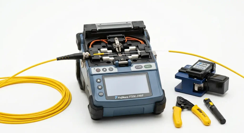
Fusion splicing uses an electric arc to melt the two fiber ends together, forming one continuous strand of glass.
How it works: A fusion splicer aligns the fibers precisely (either by their cores or claddings), applies a controlled arc to heat them to the melting point, and pushes them together. After cooling, the joint is a solid glass-to-glass weld.
Limitations
- High upfront investment in a fusion splicer and cleaver
- Needs power, a clean workspace, and trained technicians
- Less convenient for a single quick repair in difficult locations
Strengths
- Very low loss, typically 0.02–0.1 dB
- Excellent return loss, so back-reflection is negligible
- Strong, stable, and suited for the life of the network
- Low cost per splice once you own the machine
Mechanical Splicing: Aligning, Not Melting
A mechanical splice holds two cleaved fibers in a precision alignment sleeve, usually a V-groove, and clamps them together. A small amount of index-matching gel fills the gap between the fiber ends to reduce reflection.
How it works: There is no arc and no heat. The fibers touch inside the splice body, and the clamp keeps them aligned.
Limitations
- Higher loss, typically 0.1–0.5 dB
- Higher reflection than fusion splices
- Higher cost per splice, which adds up on large projects
- Gel can degrade over time in harsh conditions
Strengths
- No expensive splicer required, just a cleaver and stripping tools
- Fast and simple, with minimal training
- Works well for emergency repairs and tight spaces
- Reusable in many designs, so a splice can be adjusted
Quick Comparison
| Fusion Splice | Mechanical Splice | |
| Typical loss | 0.02–0.1 dB | 0.1–0.5 dB |
| Equipment cost | High | Low |
| Cost per splice | Low | Higher |
| Best for | Permanent, high-performance links | Repairs, small jobs, temporary fixes |
How to Fusion Splice Fiber: Step by Step
- Prepare the cable. Remove the outer jacket and any strength members or buffer tubes, exposing the coated fiber.
- Slide on the protection sleeve. Thread a heat-shrink splice sleeve onto one Fusion and Mechanical Splicing. It cannot be added afterward.
- Strip the coating. Use a fiber stripper to remove the 250 µm acrylate coating, leaving about 30–40 mm of bare glass.
- Clean the fiber. Wipe with a lint-free wipe and high-purity isopropyl alcohol until it squeaks lightly.
- Cleave. Use a precision cleaver for a flat, perpendicular end-face. A cleave angle under 1° is the target. Do not let the cleaved end touch anything.
- Load the Fusion and Mechanical Splicing. PlaceFusion and Mechanical Splicing into the splicer’s V-grooves and close the covers.
- Align and splice. Start the program. The splicer inspects the end-faces, aligns the cores, and fires the arc.
- Check the result. Review the estimated loss shown on screen and the image of the splice. Re-do it if loss is high or a bubble, thin spot, or misalignment appears.
- Proof test. Many splicers apply a tension test automatically to confirm the joint’s strength.
- Protect the splice. Slide the sleeve over the joint and heat it in the Fusion and Mechanical Splicing oven.
- Store in a tray. Place the sleeve in a splice tray, and route the fiber with a gentle bend radius.
How to Make a Mechanical Splice
- Strip, clean, and cleave both fibers exactly as above.
- Insert the first fiber into the splice body until it reaches the stop.
- Insert the second fiber from the opposite side so the ends meet in the middle.
- Close the cam or clamp to lock the fibers in place.
- Verify the joint with a visual fault locator or power meter, and secure it in the tray.
The cleave quality is just as important here. A poor cleave causes a gap and high loss.
Which Method Should You Choose?
Choose fusion splicing when:
- Building new FTTH, backbone, or data center links
- You need the lowest loss and the longest-term stability
- The project has dozens or hundreds of splices
- Loss budgets are tight, such as long-distance or high-split-ratio PON links
Choose mechanical splicing when:
- You need a quick temporary or emergency repair
- The job is small and does not justify buying a splicer
- The environment makes fusion splicing difficult
- You are training or testing, where reuse is helpful
For most professional installations, fusion splicing is the standard. Mechanical splices are valuable as a practical backup.
Common Splicing Mistakes
- Forgetting the sleeve before splicing. This forces a redo.
- Poor cleaving. Chipped or angled end-faces are the leading cause of high loss.
- Dirty fiber or contaminated V-grooves. Dust causes bubbles and weak joints.
- Skipping the splicer’s electrode check. Worn electrodes produce inconsistent arcs.
- Bending the fiber too sharply when routing in the tray, which adds loss later.
- Not testing afterward. Always verify with an OTDR.
After Splicing: Test and Organize
A splice is only finished when it has been tested. Use an OTDR to confirm each splice meets the loss target and to document the results. See our guide on how to test fiber with an OTDR for reading splice events on the trace.
Then house the splices properly. Quality fiber distribution & termination boxes include splice trays that hold sleeves securely, protect fibers from stress, and keep slack organized.
Conclusion
Fusion splicing delivers the lowest loss and the most durable joint, making it the professional standard for permanent networks. Mechanical splicing trades some performance for speed and low equipment cost, which suits repairs and small jobs. Whichever method you use, careful stripping, cleaning, and cleaving make the difference between a clean link and a troublesome one.